 Capcom PPUs, the CPS-A and CPS-B (from The Book of CP-System)
The graphic pipeline relies on a massive 32-bit data bus, powered by dual-channel GFX ROMs. It is really a beat compared to a SNES.
Capcom PPUs, the CPS-A and CPS-B (from The Book of CP-System)
The graphic pipeline relies on a massive 32-bit data bus, powered by dual-channel GFX ROMs. It is really a beat compared to a SNES.
The last article discussed the hardware of the Super Nintendo's graphic system. This one describes how these components collaborate to render sprites and backgrounds.
The most interesting thing I learned while researching this topic was how limitations such as the number of layers in a mode, the depth (bits-per-pixel) of each layer, and the maximum number of sprites on a line, all find their root in the latency of a single component.
The SNES belong to an era where consoles had no framebuffer. A field is rendered line by line and each pixel color is generated just-in-time, exactly when the CRT needs it. In the video system article we saw how the SNES video dot clock is 5,369,317Hz. This means it must come up with a color every 1,000,000,000ns / 5,369,317 = 186.2ns and send it to the CRT, no matter what.
To generate a pixel, the SNES needs to retrieve background and sprite descriptors, then get the actual color palette-index. The problem is that accessing the VRAM takes time. A very long time. If we lookup the VRAM chips datasheet used in the SNES, we see an access time of 100ns. This means the PPUs can issue one single VRAM read per pixel.
Described as is, it sounds impossible. It they can read only once, how can the PPUs handle four layers? How can they also retrieve sprite pixels on top of the layers?
A tilemap (a.k.a background, a.k.a layer) is described by tilemap entries[1], stored in VRAM. An entry is 16 bits and gives the address of a 8x8 tile[2] plus properties such as palette, flip-bits, and priority. Depending on the mode, tiles have different bits-per-pixel (bpp), from 2bpp all the way up to 8bpp.
To generate each pixel, the PPU2 needs to retrieve the palette-index of all layers, compose (pick one) according to transparency and priority, get the color from the index via the palette, and then issue a color toward the CRT.
In the table below is listed all the modes supported by the SNES[3] along with the palette-index depth of each layer. Notice how the more layers supported, the lower the bpp. This limitation entirely comes from the VRAM latency which limits the bandwidth.
| Video Mode | BG 0 | BG 1 | BG 2 | BG 3 |
|---|---|---|---|---|
| 0 | 2bpp | 2bpp | 2bpp | 2bpp |
| 1 | 4bpp | 4bpp | 2bpp | |
| 2 | 4bpp | 4bpp | ||
| 3 | 8bpp | 4bpp | ||
| 4 | 8bpp | 2bpp | ||
| 5 | 4bpp | 2bpp | ||
| 6 | 4bpp | |||
| 7 | 8bpp | EXTBG |
What is this EXTBG in Mode 7? It is a duplicate of layer BG0 with different priority. It allows to sandwich the sprites. In Contra 3, that is how player sprites can go under the bridge in level 2![4]
One read per pixel is not doable but the PPUs have internal memory to amortize the cost. The PPU2 starts receiving VRAM data before it draws the first pixel on a line and memorizes it.
Let's see how this works in detail and do the latency math to make sure it checks.
Mode 0 has four layers. This means accessing four 16-bit tilemap entries per pixel. Since the bus is 16-bit wide, the PPU can do it in four reads. Already the VRAM access time budget is blown up (4 x 100ns = 400ns)
For each tilemap entry, the palette-index must be fetched from the referenced tile. A tile line is 8 pixels wide and in mode 0 tiles use 2bpp. A 16-bit read retrieves 8 pixels (a full tile line). Let's do the math.
1 read -> BG 0 tilemap entry
1 read -> BG 1 tilemap entry
1 read -> BG 2 tilemap entry
1 read -> BG 3 tilemap entry
1 read -> 8 pixels of BG0 tile
1 read -> 8 pixels of BG1 tile
1 read -> 8 pixels of BG2 tile
1 read -> 8 pixels of BG3 tile
===============================
8 read -> Can generate 8 pixels
It barely fits in the time budget, but it works! By starting 8 pixels early, the PPUs can issue 8 reads, remember each result, and then generate 8 pixels over the next 8 dot clock with zero access to the VRAM. This process can be repeated over and over until a full line is drawn.
To retrieve 8 pixels in one 16-bit read for a 2bbp layer, the SNES mandates background tiles to be layed out in an advantageous way. It is called planar[5] and one chip holds high-bytes while the other holds low-bytes.
Likewise, tilemap entries are stored according to the VRAM interleave we saw in last article to guarantee a full entry can be retrieved in a single read, using the same address on both address buses.
Mode 1 (the most used mode by games) is made of three layers. Two use 4bpp while the third uses 2bpp. Let's do the math. Again.
1 read -> BG 0 tilemap entry
1 read -> BG 1 tilemap entry
1 read -> BG 2 tilemap entry
1 read -> 4 pixels of BG0 tile
1 read -> 4 pixels of BG0 tile
1 read -> 4 pixels of BG1 tile
1 read -> 4 pixels of BG1 tile
1 read -> 8 pixels of BG2 tile
===============================
8 read -> Can generate 8 pixels
Again, it barely fits but the latency checks!
To retrieve 4 pixels in one 16-bit read, the SNES mandates 4bpp background tile to be layout in yet another planar mode where two planes are stored in one byte. One byte is stored in each VRAM chip[6].
In Mode 3, one layer uses a whooping 8bpp and another layer uses 2bpp.
1 read -> BG 0 tilemap entry
1 read -> BG 1 tilemap entry
1 read -> 2 pixels of BG0 tile
1 read -> 2 pixels of BG0 tile
1 read -> 2 pixels of BG0 tile
1 read -> 2 pixels of BG0 tile
1 read -> 8 pixels of BG1 tile
===============================
7 read -> Can generate 8 pixels
I'm sure you got the idea.
Mode 7 is special. Even though it uses only one layer at 8bpp, it is the most difficult to implement.
The math worked in all previous examples because the 16-bit bus allowed to retrieve several adjacent pixels at once. This trick is no longer available in Mode 7 because its layer can be rotated and scaled. E.g.: there is nothing to gain in bulk retrieving horizontally consecutive pixels if the layer is rotated 90°.
This problem, Nintendo solved it with the weird address lines we saw in the hardware article. In mode 7, the VRAM is set up differently. Only 16 KiB is used in each chip. One chip contains the tilemap entries while the other contains the tiles[7][8].
With its ability to address each chip individually, the PPus can emit 1 pixel per cycle.
Time -2: Get tilemap for Pixel 0  (VRAM chip1)

Time -1: Get tilemap for Pixel 1  (VRAM chip1)
Time -1: Get tile    for Pixel 0                 (VRAM chip2)

Time 0: Emit Pixel 0
Time 0: Get tilemap for Pixel 2   (VRAM chip1)
Time 0: Get tile    for Pixel 1                  (VRAM chip2)

Time 1: Emit Pixel 1
Time 1: Get tilemap for Pixel 3   (VRAM chip1)
Time 1: Get tile    for Pixel 2                  (VRAM chip2)
Two reads result in two pixels, which is 1 access per pixel. Again, the timing works.
The SNES supports up to 128 sprites on screen (more with sprite multiplexing). They are made of 15 colors + transparency (4bpp) with width of either 8, 16, 32, or 64 pixels.
Sprite attributes are stored in the OAM (inside the PPU1) but the sprite colors still need to be retrieved from VRAM. That is a problem since the whole VRAM bandwidth is consumed by the backgrounds rendering.
During active screen rendering, the video RAM of the PPUs is completely inaccessible to the SNES CPU: you cannot even read what is being fetched while the PPUs access this memory.
- byuu[9]
A SNES line is made of 341 dots. 256 of them have a color while 85 are blanked.

The PPU1 leverages that HBLANK time where the VRAM is not used to fetch as much sprite data as it can. It builds a line of sprite layer and cache it in a structure called a sprite line buffer.
The line buffer is made of 8-pixel groups called slivers (that is 4 bytes a.k.a two VRAM access). The PPU1 line buffer has space for 34 slivers. That means a scanline can feature at most 34 sprites or 34 * 8 = 272 sprite pixels, whichever limit is reached first[10].
The topic of sprite rendering is fascinating. It is worth a side-quest to explore how other machines of the early 90s did it.
| Sprite technique | Machine | Details |
|---|---|---|
| Software | Amstrad CPC | Blood |
| PC | Sweat | |
| Atari ST | Tears | |
| Sprite units | C64 | 8 sprite units, Unit non-reusable on line[11][12] |
| Amiga | 8 sprite units. Unit reusable on line[13][14][15]. | |
| Line buffer | SNES | 128 sprites, max per line: 32 sprites / 272 pixels. |
| Sega Genesis | 80 sprites, max per line: 20 sprites / 320 pixels[16][17] | |
| Double line buffer | Neo-Geo | 381 sprites, 96 per lines[18] |
| Sprite framebuffer | CPS-1 | 256 sprites. No per-line limitation. |
As a previous owner of an Amstrad CPC, then Atari ST, then PC it is not something I remember fondly. Perhaps readers will relate and understand why I love the SNES so much.
Machines released before the SNES and the Genesis used a "sprites unit" which intercepted the raster line to overlay sprites on top of the background. This approach made sprite fetching compete with background fetching while a line was rendered.
A cool technique allowed to draw more sprites than sprites unit in a frame via something called multiplexing. The idea is to reuse an unit lower on the screen when it is no longer needed (all the sprite height has been rendered).
The Amiga was even more powerful since it is able to multiplex sprite-units on the same line[19] and completely cover the screen with a sprite layer[20].
Line buffers are not only used by the Super Nintendo. It is also what the Sega Genesis uses to render sprites.
Note that the SNES did not saturate HBLANK with sprite retrieval. Fetching 34 slivers takes 100ns * 2 * 34 = 6800ns. HBLANK lasts 85 * 186.2ns = 15,827ns. This leaves 15,827 - 6,800 = 9,027ns for tricks. E.g.: Gorgeous raster effects where each lines of a layer is shifted differently during HBLANK as demonstrated in see Contra 3 below.
 Contra III (1992)
A way to take things to the next level is to double the sprite line buffer.
With a double line buffer, the machine is always rendering sprites. One buffer is fed to the CRT while the other is generated. That is the way the Neo Geo works.
The huge advantage over a single line buffer is that the PPU can retrieve sprites not only for HBLANK duration but for the entire duration of a line.
This design, along with massive PPU data lines directly connected to MiB of GFX-ROM, allow the Neo-Geo a maximum of 96 sprites per line max (3x what the SNES can do).
 Source (superadventuresingaming.blogspot.com). Metal Slug
If the PPU fetch sprites for the next line, how to fetch the background for the current line? Answer: It doesn't. The Neo-geo has no background, everything is a sprite.
What is better than a double line buffer? A full screen sprite buffer which I call a sprite framebuffer.
That is a massively expensive architecture since it requires enough VRAM to cover the whole screen (twice since it is double buffered). It was a very pricey choice in the 90s. Not only because RAM was expensive but because VRAM was made of SRAM (vs DRAM).
Capcom spared no expense when it came to craft its arcade CPS1 cabinet. The gigantic arcade sprites of Street Fighter II and Final Fight speak for themselves.
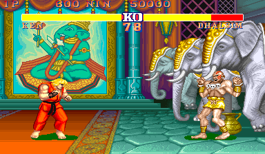 Street Fighter II (1991)
The advantage of a sprite framebuffer is dual. With a sprite framebuffer the system has a full frame to fetch all the sprites which allows more of them. As a result, the CPS-1 supports 256 sprites, made of 16x16 tiles (4bpp). More importantly, there is no per-line limitation.
At this point, we have a full picture of what happens in the PPUs. To draw a line, the PPU1 drives the PPU2 by setting the VRAM address lines, the PPU2 consumes the BG layers on the VRAM data lines. Through its direct lines to the PPU2, the PPU1 streams the sprite layer built during the last HBLANK.
Composition of all five layers happens on the PPU2. The emerging palette-index is looked up against the palette and an RGB color is sent to the CRT.

Once again, the architecture is very similar to the CPS1 PPUs. In Capcom's machine, the CPS-A drive the CPS-B to draw a sprite framebuffer while it fills another sprite framebuffer to the CPS-B. The CPS-B does all the composition.
Capcom PPUs, the CPS-A and CPS-B (from The Book of CP-System)
The graphic pipeline relies on a massive 32-bit data bus, powered by dual-channel GFX ROMs. It is really a beat compared to a SNES.
This article doesn't touch the topic of PPU programming because it is covered extensively on snes.nesdev.org. There is also a brilliant Youtube series by "Retro Game Mechanics Explained" which you should not miss.